
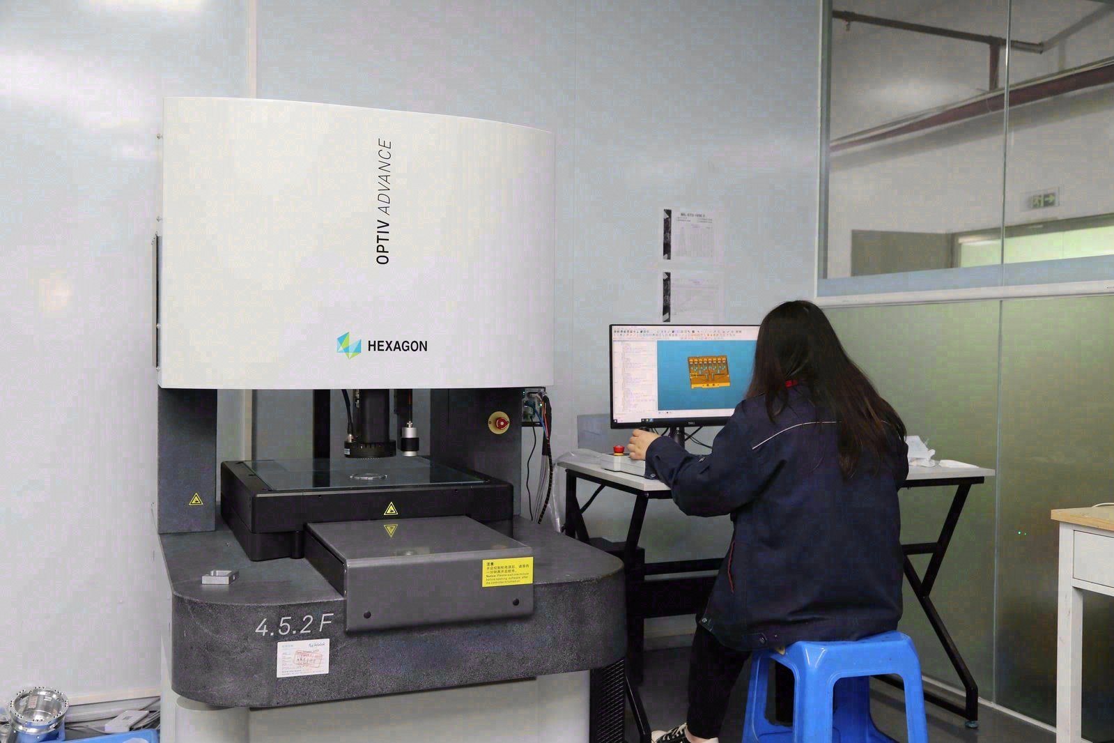
Tolerance and surface finish are where machining buyers and suppliers most often talk past each other. The buyer types numbers into CAD without knowing what the process holds; the supplier quotes a drawing without challenging it; and the gap shows up at incoming inspection. This guide sets out the realistic envelope — what production machining holds, what grinding adds, what finish values mean — and the drafting habits that keep the drawing aligned with the process, so the part arrives measured, verified, and on spec.
What tolerances are actually realistic on CNC machined parts?
Start with the production envelope, because everything else hangs off it. CNC milling and turning hold ±0.003 mm on machined features — a tight but production-realistic band that a capable manufacturer holds across a run, not just on a first piece. Where a part needs more — a bearing seat, a sealing surface, a diameter that controls a fit — precision grinding reaches ±0.002 mm. Those two numbers are the honest floor: claims inside the envelope are credible, and claims far beyond it need evidence rather than enthusiasm.
Tolerance is only real if it holds across the run, which is what process capability measures. Ppk ≥ 1.67 at the initial study on key characteristics and Cpk ≥ 1.33 on general characteristics. Capability is reported per characteristic: every report names the feature, its tolerance band, the sample size, the sigma method, and the study window. Is the standard a serious manufacturer quotes, because it means the process sits inside the tolerance band with margin, run after run. A supplier that gives you a Cpk number with measured data is proving the tolerance; one that gives you only a paragraph is asking you to trust a promise.
On a representative length characteristic, the SPC record at this machining manufacturer shows Cpk of 1.851 — comfortably above the 1.67 key-characteristic target. That kind of measured chart is what an auditor reviews, and it is the evidence a buyer should ask for before volume rather than after a bad batch.
One more check on that number: the 0.4 mm band behind it is wide by design. Hold the same process spread against a ±0.005 mm feature and it fails outright, so read this figure as evidence about one characteristic on one run, not as a blanket tolerance claim.
What is the difference between size tolerance and geometric tolerance?
Size tolerance controls a dimension's value — a diameter, a length, a thickness. Geometric tolerance — GD&T — controls how the feature sits in space: its form, orientation, and location relative to a datum. Flatness, roundness, position, and cylindricity are geometric controls, and each one needs a datum to be measured from, because a control without an origin cannot be measured consistently.
The distinction matters because a part can be the right size and still fail to work. A bore can measure exactly on its diameter and still be out of position relative to the mating shaft; a face can be the right distance and still be angled. On machined parts, the geometric callouts are often the ones that make the assembly function, and they are the ones that decide whether the part is measured on a CMM rather than with a caliper.
Write geometric controls with the datum scheme the machining process will use, so the manufacturer and the CMM work from one origin. A part drawn with a clear datum structure is cheaper to make and cheaper to inspect than one where the controls float without a reference, and it is far less likely to produce a dispute at your dock.
What surface finish values should a drawing actually carry?
Surface finish is stated in Ra — the arithmetic average of the surface profile — and the drawing should carry a number rather than a word. As a practical guide: a standard as-machined finish commonly lands around Ra 1.6–3.2 µm; a finer as-machined finish reaches Ra 0.8 µm with a clean finishing pass; and grinding or polishing reaches lower values — Ra 0.4 µm and below — on the surfaces that need them. Values inside those bands are routine; values beyond them are process steps with their own cost.
| Ra value (µm) | Typical process | Typical use |
|---|---|---|
| 3.2 | Standard milling or turning | Non-functional faces, general surfaces |
| 1.6 | Fine machining pass | Common general-purpose finish |
| 0.8 | Light finishing pass | Sealing and wear surfaces |
| 0.4 | Grinding or polishing | Bearing seats, instrument surfaces |
| 0.2 and below | Precision grinding, lapping | Critical precision surfaces |
State the value you need and let the finish strategy follow the material. A fine finish on aluminum may be one finishing pass; the same value on stainless may need two passes and a profilometer check. A finish specified as "good finish" is a guess the manufacturer must price defensively; one stated as Ra 0.8 µm is a specification it can quote and verify.
How do tolerance and finish interact on a machined part?
Tolerance and finish are not independent — they share the same process chain. A surface that needs a fine finish on a sealing diameter usually gets ground rather than finished by a machining pass, and grinding changes the tolerance story: the process that reaches ±0.002 mm is the same process that reaches the fine finish. Specify the pair together so the manufacturer plans one coherent chain rather than discovering the interaction at the machine.
Coatings add a second interaction. An anodize layer on aluminum adds a few microns to the surface, which is irrelevant on a clearance face and critical on a fit diameter; a drawing that calls both anodize and a tight diameter has to decide whether the diameter is machined before coating, after coating, or masked. State the coating and the tolerance together so the manufacturer can plan the order of operations.
Measurement temperature is the quiet third factor. Aluminum expands roughly 23 µm/m per degree C, so a precision part machined in a warm shop can measure differently in a cold inspection room. Agree the measurement standard — 20 C is the reference — and both the factory and your incoming inspection should measure the critical features at it. On tight work this single discipline prevents more disputes than any other.
What is a general tolerance block, and why should the drawing have one?
A general tolerance block — ISO 2768-M or an equivalent — sets the default tolerance for every dimension that carries no callout. It exists because drawings cannot call out every feature, and without a block the supplier must assume one. The danger is that the assumption is often tighter than the design needs, and the supplier prices the whole part as if every uncalled dimension were tight.
State the block on the drawing, and keep it sensible. A general block of ±0.1 mm or the ISO 2768-M equivalent tells the supplier that the uncalled dimensions are loose, which lets it concentrate cost where the callouts actually are. The tight bands then carry the price, and the price reflects the function rather than the fear.
That discipline is the single biggest lever on a machining quote. Tolerancing only the features that control function — the fits, the seals, the locations that matter — and letting the general block carry the rest cuts cost without changing how the part works. Marking every dimension critical is the most common first-order mistake, and it is exactly what a DFM review should flag before you pay for it.
How much does a tight callout actually add to the price?
Substantially, and the curve is steep rather than linear. Every feature pulled to the tight end of the envelope adds finishing passes, adds inspection time on the CMM, and adds the risk of scrap when the process drifts. On a low-volume order — where a machining manufacturer earns much of its work — that cost is never amortized across a big batch, so a few over-tight callouts can move a quote by a large percentage.
The rule is to spend tightness where function demands. A bearing seat, a sealing face, or a feature that locates another component earns its ±0.003 mm or its grinding step; a cosmetic corner or an inherited template dimension does not. The DFM review that comes with a quote should name the callouts that cost money without adding function, and a supplier that does is doing the engineering rather than just pricing the drawing.
Geometric controls cost the same way, through the inspection plan. Position, cylindricity, and concentricity callouts put the feature on the CMM and add measurement time on every piece or every lot. A drawing dense with geometric controls inspects slowly and costs accordingly, which is another reason to write only the controls that make the assembly work.
How is a tolerance or finish actually verified?
Tolerance claims are only as good as the measurement behind them. Critical dimensions are verified on CMMs against the drawing's datum scheme — the machine builds its coordinate system from the datums and measures each feature against it, so the report proves the geometry rather than assuming it. Surface finish is measured with a profilometer, which traces the surface and reports the Ra, rather than judged by eye.
The reports are the evidence, and they should ship with the parts: CMM dimensional reports, SPC charts, and material certificates. On a first article from a new manufacturer, read the report against the part yourself and spot-check the critical dimensions with your own instruments where you can. A report that ties back to the drawing datums and agrees with your measurement converts a tolerance claim into a proven one.
The measurement architecture behind the reports is described in the quality and measurement guide, and the verification sequence for a new supplier is covered in the sourcing verification guide.
How do the tolerances map to the machining processes?
Matching the callout to the process is where the drawing either costs money or saves it. Milling and turning hold ±0.003 mm on most features at production speed; a feature that genuinely needs the grinding envelope moves to ±0.002 mm with a grinding step and its own setup. Threads, holes, and keyways each have their own realistic bands, and a drawing that respects them gets machined at production speed rather than at a crawl.
| Process | Realistic tolerance | Typical use |
|---|---|---|
| CNC milling | ±0.003 mm | Prismatic features, housings, brackets |
| CNC turning | ±0.003 mm | Diameters, shafts, pins, bushings |
| Precision grinding | ±0.002 mm | Bearing seats, sealing and seating surfaces |
| Threads | Standard fit classes | Fasteners and fittings; non-standard threads add steps |
Where a dimension cannot be reliably held, the honest response is to flag it in the DFM review before cutting, not to discover it on the first article. A manufacturer that flags a callout is protecting you; one that accepts every number without comment is setting up the non-conformance it will ship you later. The tolerance and finish choices also interact with the material decision, which alloy to specify is a separate question, and it is covered in the aluminum vs stainless decision guide.
How do you keep a tolerance claim honest across the run?
A first article proves the setup was right on one day; the run proves the process held. That is the role of SPC data and the capability number: Ppk ≥ 1.67 at the initial study on key characteristics and Cpk ≥ 1.33 on general characteristics. Capability is reported per characteristic: every report names the feature, its tolerance band, the sample size, the sigma method, and the study window. Tells you the process sat inside the band with margin across the lot, not just on the piece that shipped. Ask for the data on production lots, not only on the prototype, and require it per lot on regulated work.
Keep the measurement standard identical from prototype to production. If your quality system measures critical features at 20 C against the drawing datums on the prototype, it needs the same on every production lot — changing the standard between stages is how parts drift into a dispute. Agree the standard when you approve the first article, and hold it for the life of the program.
And verify the claim early with a sample order at a 1-piece MOQ. A CMM report on your own part, read against your own drawing, is the cheapest proof that a machining manufacturer holds what it quotes, and it is exactly the gate to run before volume moves. The cost structure around the tolerance you specify is worked through in the machining manufacturer cost guide.
Frequently Asked Questions
What tolerances are realistic on CNC machined parts?
Production capability on milled and turned features is ±0.003 mm, with ±0.002 mm reachable by precision grinding on sealing and seating surfaces. Process capability of Ppk ≥ 1.67 at the initial study on key characteristics and Cpk ≥ 1.33 on general characteristics. Capability is reported per characteristic: every report names the feature, its tolerance band, the sample size, the sigma method, and the study window. Shows the tolerance holds across the run, not just on one piece.
What is the difference between size tolerance and geometric tolerance?
Size tolerance controls a dimension's value; geometric tolerance (GD&T) controls form, orientation, and location — flatness, roundness, position, cylindricity. A part can be the right size and still fail a fit if a feature is out of position, which is why geometric callouts need a datum to measure from.
What surface finish should I specify on a machined drawing?
State the value in Ra. A standard as-machined finish commonly lands around Ra 1.6–3.2 µm; finer as-machined finishes reach Ra 0.8 µm with a finishing pass; and grinding or polishing reaches lower values on the surfaces that need them. A finish specified as good is a guess; one stated in Ra is a specification.
How much does a tight tolerance add to the price?
Substantially, and the curve is steep. Every feature pulled tight adds finishing passes, inspection, and the risk of scrap, and on a low-volume order that cost is never amortized. Put the tight bands where the part mates or seals and let the rest ride the general block — a tolerance tighter than function needs is pure cost.
What is a general tolerance block, and why should the drawing have one?
A general block such as ISO 2768-M sets the default tolerance for every dimension without a callout. Without one, the supplier must assume a standard — often tighter than you need — and price accordingly. State the block on the drawing so only the functional features carry the expensive tight bands.
How is a tolerance or finish verified?
Critical dimensions are verified on CMMs against the drawing's datum scheme, and surface finish is measured with a profilometer rather than judged by eye. The reports ship with the parts, and process capability of Ppk ≥ 1.67 at the initial study on key characteristics and Cpk ≥ 1.33 on general characteristics. Capability is reported per characteristic: every report names the feature, its tolerance band, the sample size, the sigma method, and the study window. Shows the tolerance held across the run.
Do surface finish and tolerance interact on a machined part?
Yes. A finish that needs grinding on a sealing surface changes the process step and therefore the achievable size tolerance; a coating such as anodize adds a layer that affects fit-critical diameters. State finish and tolerance together on the drawing so the process chain is planned for both.
How do I keep tolerance claims honest from a machining manufacturer?
Ask for measurement evidence from a real job, not a capability statement, and verify it with a sample order at a 1-piece MOQ. Read the CMM report against the drawing and spot-check the critical dimensions yourself — a report that agrees with your own measurement converts a tolerance claim into evidence.
Want your tolerance callouts read against the process?
Email the model and the toleranced drawing to [email protected] or call +86 13126536955. You will get a DFM review that confirms or flags each callout, with the realistic finish and tolerance envelope stated before you commit.